Typical applications
 3 phase isolating transformer according to IEC/EN61558-2-4 for general applications, e.g. for providing electrical (galvanic) isolation according to VDE0700/EN60335 regulations or network supply transformer (e.g. TN network system).
Specifications
3 phase isolating transformer according to EN61558-2-4. protection class I ready. Due to innovative vacuum impregnation in polyester varnish, the noise level is extraordinary low. Screw terminals are contact proof according to VBG4.
Standard switching matrix: Yyn0 (max. typical star load of phase current: approx. 10%). Switching matrix: Please note the distinction between different voltages (e.g. phase voltage, line voltage). Final operation position must allow natural convection through coolant bores. For further information, don’t hesitate to contact us.
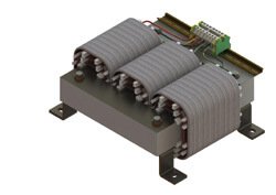
Transformer provides 2 loops for safe transportation or craning.
3 phase isolating transformer according to IEC/EN61558-2-4
natural convection through coolant bore; without coil former; winding on glass-fibre; reinforced plastic profiles
| Voltage range | 200 V … 550 V | |
| Rated frequency | 50/60 Hz | |
| power range (contract works!) | 5,0kVA … 35,0kVA | |
| Max. ambient power | 40°C | |
| UL-Insulation system (optional) | OBJY2.E181051 | |
| Insulation class (IEC85) | B 130°C | |
| Fire protection class | UL94HB (V-0 possible) | |
| Open transformer – degree of protection | IP00 | |
| Protection class (ready) | I |
- Transformer completely vacuum impregnated
- Standard switching matrix Yyn0 (typical star load approx. 10%)
- attachment with assembly brackets for Horizontal mounting version
- Screw terminals contact proof according to BGV A3
- Ready for horizontal mounting including angle brackets
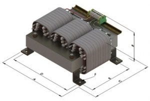
| Rated power kVA |
Dimensions approx. mm |
Copper weight
KG |
Total weight
KG
|
Size | Type | |||||
|
A
|
B
|
C
|
D
|
E
|
F
|
|||||
|
6,3
|
394 | 185 |
325
|
358
|
240
|
9,0×14,0
|
12,0
|
45,0
|
3UI 300/300/63 |
DTL0630
|
| 8,0 | 394 | 200 | 325 | 358 | 240 |
9,0×14,0
|
12,9 | 52,0 | 3UI 300/300/78 | DTL0800 |
| 10,0 | 452 | 200 |
375
|
408 | 280 |
13,0×20,0
|
12,0 | 62,0 | 3UI 350/350/73 | DTL1000 |
| 12,5 | 452 | 215 |
375
|
408 | 280 |
13,0×20,0
|
14,5 | 76,0 | 3UI 350/350/88 | DTL1250 |
|
16,0
|
526 | 215 | 430 | 472 | 320 |
13,0×20,0
|
17,9 | 92,0 | 3UI 400/400/83 | DTL1600 |
| 20,0 | 526 | 215 |
430
|
472
|
320
|
13,0×20,0
|
24,0
|
98,0 | 3UI 400/400/83 | DTL2000 |
| 25,0 | 526 | 225 | 430 | 472 | 320 | 13,0×20,0 | 31,0 | 114,0 | 3UI 400/400/93 | DTL2500 |
| 30,0 | 526 | 245 | 435 | 472 | 320 | 13,0×20,0 | 41,0 | 138,5 | 3UI 400/400/110 | DTL3000 |
| 35,0 | 526 | 290 | 435 | 472 | 320 | 13,0×20,0 | 36,5 | 161,0 | 3UI 400/400/140 | DTL3500 |
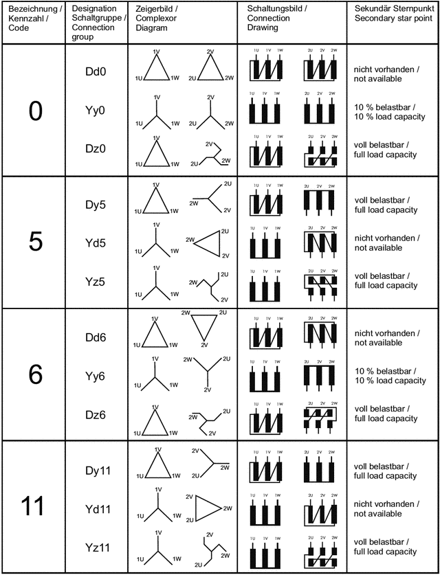
3 Phase Isolating Transformers Circuits and Circuit Designs
3 phase isolation transformers offer various possibilities to connect PRIMARY and SECUNDARY winding.
Each design allows specific transformer characteristics. See the following table for preferred circuit designs.
- Neutral wire “N“ or “n”. Percentage of neutral wire current allways refers to nominal current of phase conductor.
- Please mind:
- Secundary star circuit allows load on neutral wire.
- Parallel connection of transformers must comply to following criteria:
- Nominal voltage and rated frequency
- Circuit design
- Short circuit voltages
- Ratio of rated loads should not extend 3:1