


typical applications
1 phase pre-circuit transformer according to IEC/EN61558-2-13 (autotransformer) for general applications without the need of a galvanic isolation, e.g. for transforming typical mains voltage to other voltages needed by tools, machinery or other devices.
VT pre-circuit transformers and other autotransformers do not provide any electrical protection due to the lack of galvanic isolation between input and output windings.
Specifications
Pre-circuit transformers provide windings suitable for following configurations:
- 0 V … 110 V / 115 V
- 127 V / 133 V
- 220 V / 230 V
- 240 V
These terminals can be used either as input- or output voltage terminals. Output winding must provide external fuse for safety reasons (see table for details)
- Terminal tag connections
- Vacuum impregnation in polyester varnish – low operating noise.
1 Phase Autotransformer
with terminal tag connections IEC/EN61558-2-13
| Voltage range / Input, Output | 0-110/115V
127/133V 220/230V 240V |
|
| Rated frequency | 50/60 Hz | |
| Power range | 25 VA … 2500 VA | |
| Max. ambient temperature | 40°C | |
| UL Insulation System (optional) | OBJY2.E181051 | |
| Insulation class (IEC85) | B 130°C | |
| Fire protection class | UL94HB (V-0 possible) | |
| kind of protection | IP00 | |
| degree of protection | I ready |
- welded earth conductor 2 flat connection 6,3 x 0,8mm
- attachment über Montagewinkel in beliebiger Einbaulage
- Screw terminals contact proof according to BGV A3
- Transformer completely vacuum impregnated
| Power VA |
Max. fuse for output winding
(G delay fuse according to IEC127) A
|
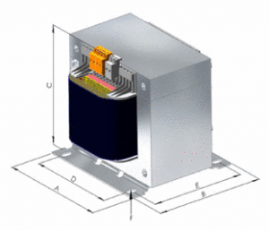
Dimensions
approx. mm
|
Copper
weight KG
|
Total
weight KG
|
Type and
Ordering No.
|
||||||||
|
110/115V
|
127/133V | 220/230V | 240V | A |
B
|
C
|
D
|
E
|
F
|
||||
| 25 | 0,16 | 0,16 | 0,10 | 0,10 | 54 | 45 | 49 | 44 | 34 | 3,6×7,0 | 0,07 | 0,39 | VT002 |
|
50
|
0,315 | 0,25 | 0,20 | 0,20 | 60 | 47 | 59 | 44 | 36 | 3,6×7,0 | 0,10 | 0,51 | VT005 |
|
75
|
0,40 | 0,40 | 0,315 | 0,315 | 66 | 60 | 59 | 50 | 49 | 4,8×9,0 | 0,15 | 0,90 | VT007 |
Explanation and vector-groups to applicate 1 phase and 3 phase autotransformers
Autotransformers do not provide galvanic isolation.
They have electroconductive connection between input and output winding. It`s not allowed to take autotransformers for electrically protective separation.
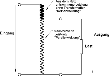
If difference between input voltage and output voltage is small:
- mains power may be higher
- transformed power is lower
- size can be reduced (core, copper winding)
Since the high-voltage and low-voltage windings in an autotransformer share a common portion of the same winding, the size and material costs can be reduced.
Example shows 90% power saving compared to an isolating transformer
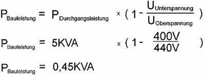
Equation to calculate the requested size
Example: 1 phase autotransformer / Input voltage 440 V / Output voltage 400 V / „Rated power“ needed for application 5 kVA
Identical equation works with 3 phase transformers.
Regarding input/ output “upper“ or „lower voltage“ is independant, voltage related only for 3 phase autotransformers value of phase voltage is important.
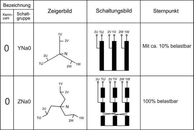
Standard circuit design of 3 phase autotransformers is YNa0. Max. load at neutral wire is approx. max. 10% of nominal current (phase current).
If 100% neutral wire load is requested, circuit design ZNa0 is manufactured.
Note: YNa0 design can be used in certain circumstances, if neutral wire at input provides full load and transformer star point is permanently connected to load. Please contact us for further informations!