


Typical applications
3 phase autotransformer according to IEC/EN61558-2-13 for general applications without the need of a galvanic isolation, e.g. for transforming typical mains voltage to other voltages needed by tools, machinery or other devices.
Autotransformers do not provide any electrical protection due to the lack of galvanic isolation between input and output windings.
Specifications
3 phase transformer according to EN61558-2-13. protection class I ready. Due to innovative vacuum impregnation in polyester varnish, the noise level is extraordinary low. Screw terminals are contact proof according to BGV A3.
Autotransformers are provided for a voltage range from 100 V up to 550 V (special voltage versions on request).
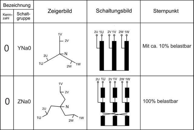
Standard switching matrix: Yan0 (typical star load approx. 10%). If typical star load should reach rated current, switching matrix Zan0 is used.
Please add switching matrix requested when ordering the transformer. For further information, don´t hesitate to contact us.
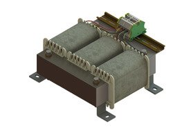
3 Phase Autotransformer, horizontal mounting version with screw type terminals IEC/EN61558-2-13
| Voltage range input / output | 100 V … 550 V | |
| Rated frequency | 50/60 Hz | |
| Power range | 250VA … 1,6kVA | |
| Output design | Standard switching matrix: YNa0
typical star load approx. 10% |
|
| Switching matrix – on request: ZNa0
typical star load 100% |
||
| Max. ambient temperature | 40°C | |
| UL Insulation System (optional) | OBJY2.E181051 | |
| Insulation class (IEC85) | B 130°C | |
| Fire protection class | UL94HB (V-0 possible) | |
| Degree of protection | IP00 | |
| Protection class | I |
- No galvanic isolation
- Ready for horizontal mounting including angle brackets
- Transformer connections: Screw terminals according to BGV A3
- Transformer completely vacuum impregnated
| Rated power kVA |
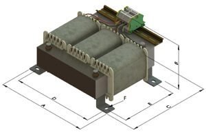
Dimensions
approx. mm
|
Copper
weight KG
|
Total
weight KG
|
Size |
Type and
Ordering No.
|
|||||
|
A
|
B*
|
C
|
D
|
E
|
F
|
|||||
|
0,25
|
156
|
73
|
140
|
140
|
100
|
5,8×9,0
|
1,30
|
3,90
|
3UI 75/26 |
DAL0025
|
| 0,40 | 156 |
90
|
140 | 140 | 100 |
5,8×9,0
|
1,60 |
5,70
|
3UI 75/41,5 | DAL0040 |
| 0,50 | 206 |
84
|
160 |
184
|
120 |
7,0×13,0
|
2,20 |
6,60
|
3UI 90/31 | DAL0050 |
|
0,63
|
206 | 95 | 160 |
184
|
120 |
7,0×13,0
|
2,80 |
8,00
|
3UI 90/41,5 | DAL0063 |
|
0,80
|
206
|
105
|
160
|
184
|
120 |
7,0×13,0
|
3,00
|
9,90
|
3UI 90/51,5 | DAL0080 |
|
1,00
|
254 | 95 |
190
|
228
|
152 |
7,0×13,0
|
4,60
|
13,50 | 3UI 114/40 | DAL0100 |
|
1,25
|
254
|
95 |
190
|
228 | 152 |
7,0×13,0
|
5,30
|
14,20 | 3UI 114/40 | DAL0125 |
|
1,60
|
290 |
100
|
200
|
258
|
160
|
9,0×13,0
|
5,70
|
15,30
|
3UI 120/41 | DAL0160 |
Please note:
*Dimension “B” indicates a reference value only. Phase current and therefore size of screw terminals used depends on transformer ratio (identical size). Coolant bore between primary and secundary winding. Winding on polyamide coil former.
Explanation and vector-groups to applicate 1 phase and 3 phase autotransformers
Autotransformers do not provide galvanic isolation.
They have electroconductive connection between input and output winding. It`s not allowed to take autotransformers for electrically protective separation.
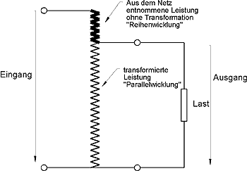
If difference between input voltage and output voltage is small:
- mains power may be higher
- transformed power is lower
- size can be reduced (core, copper winding)
Since the high-voltage and low-voltage windings in an autotransformer share a common portion of the same winding, the size and material costs can be reduced.
Example shows 90% power saving compared to an isolating transformer
Equation to calculate the requested size
Example: 1 phase autotransformer / Input voltage 440 V / Output voltage 400 V / „Rated power“ needed for application 5 kVA
Identical equation works with 3 phase transformers.
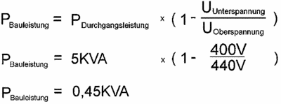
Regarding input/ output “upper“ or „lower voltage“ is independant, voltage related only for 3 phase autotransformers value of phase voltage is important.
Standard circuit design of 3 phase autotransformers is YNa0. Max. load at neutral wire is approx. max. 10% of nominal current (phase current).
If 100% neutral wire load is requested, circuit design ZNa0 is manufactured.
Note: YNa0 design can be used in certain circumstances, if neutral wire at input provides full load and transformer star point is permanently connected to load. Please contact us for further informations!