


Typical applications
3 phase isolating transformer according to IEC/EN61558-2-4 for general applications, e.g. for providing electrical (galvanic) isolation according to VDE0700/EN60335 regulations or network supply transformer (e.g. TN network system).
Specifications
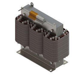
3 phase isolating transformer according to EN61558-2-4. protection class I ready. Due to innovative vacuum impregnation in polyester varnish, the noise level is extraordinary low. Screw terminals are contact proof according to VBG4.
Standard switching matrix: Yyn0 (max. typical star load of phase current: approx. 10%). Switching matrix: Please note the distinction between different voltages (e.g. phase voltage, line voltage).
Final operation position must allow natural convection through coolant bores. For further information, don´t hesitate to contact us.
Transformer provides 2 loops for safe transportation or craning.
3 Phase Isolating Transformer according to IEC/EN61558-2-4; natural convection through coolant bore, without coil former, winding on glass-fibre reinforced plastic profiles
| Voltage range / Input, Output | 200 V … 550 V | |
| Rated frequency | 50/60 Hz | |
| Power range | 5,0kVA … 35,0kVA | |
| Max. ambient temperature | 40°C | |
| UL-Insulation system (optional) | E181051 | |
| Insulation class (IEC85) | F 155°C | |
| Fire protection class | UL94HB (V-0 möglich) | |
| Open transformer – degree of protection | IP00 | |
| Protection class (ready) | I |
- Transformer completely vacuum impregnated
- Standard switching matrix Yyn0 (typical star load approx. 10%)
- Screw terminals contact proof according to VBG4
- Ready for vertical mounting – including angle brackets
| Rated power kVA |
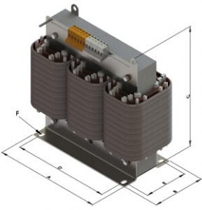
Dimensions approx. mm |
Copper
weight
KG
|
Total
weight
KG
|
Size | Type | |||||
|
A
|
B
|
C*
|
D
|
E
|
F
|
|||||
|
6,3
|
360 | 210 |
345
|
264
|
125
|
10,0×18,0
|
12,0
|
45,0
|
3UI 300/300/63 |
DTS0630
|
| 8,0 | 360 | 225 | 345 |
264
|
140 |
10,0×18,0
|
12,9 | 52,0 | 3UI 300/300/78 | DTS0800 |
| 10,0 | 420 | 240 |
395
|
316
|
143 |
12,0×18,0
|
12,0 | 62,0 | 3UI 350/350/73 | DTS1000 |
| 12,5 | 420 | 255 |
395
|
316
|
158 |
12,0×18,0
|
14,5 | 76,0 | 3UI 350/350/88 | DTS1250 |
|
16,0
|
480 | 270 |
440
|
356
|
157 |
15,0×22,0
|
17,9 | 92,0 | 3UI 400/400/83 | DTS1600 |
| 20,0 | 480 | 270 |
440
|
356
|
157
|
15,0×22,0
|
24,0
|
98,0 | 3UI 400/400/83 | DTS2000 |
| 25,0 | 480 | 280 | 450 | 356 | 167 | 15,0×22,0 | 31,0 | 114,0 | 3UI 400/400/93 | DTS2500 |
| 30,0 | 480 | 300 | 450 | 356 | 184 | 15,0×22,0 | 41,0 | 138,5 | 3UI 400/400/110 | DTS3000 |
| 35,0 | 480 | 330 | 450 | 356 | 214 | 15,0×22,0 | 36,5 | 161,0 | 3UI 400/400/140 | DTS3500
|
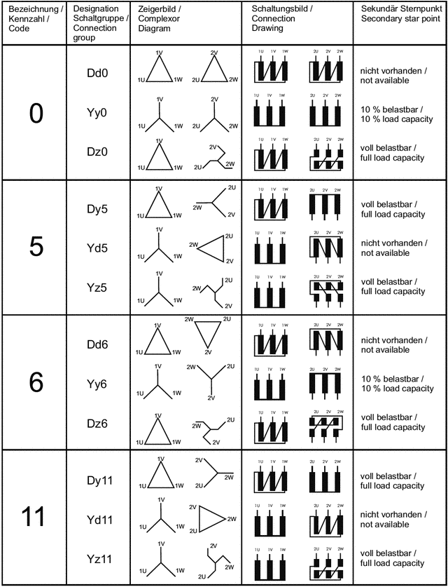
3 Phase Isolating Transformers Circuits and Circuit Designs
3 phase isolation transformers offer various possibilities to connect PRIMARY and SECUNDARY winding.
Each design allows specific transformer characteristics. See the following table for preferred circuit designs.
- Neutral wire “N“ or “n”. Percentage of neutral wire current allways refers to nominal current of phase conductor.
- Please mind:
- Secundary star circuit allows load on neutral wire.
- Parallel connection of transformers must comply to following criteria:
- Nominal voltage and rated frequency
- Circuit design
- Short circuit voltages
- Ratio of rated loads should not extend 3:1